Process flow diagram of pressure loop. Basics of a control loop Pressure control loop diagram simple pressure control loop diagram
How a Process Control Loop Works in Automatic Control Systems
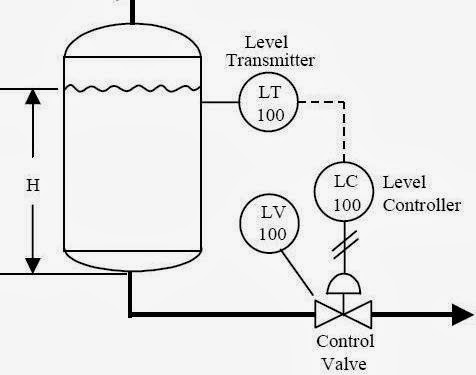
Level control loop process example sensor industry guidelines selection 2011 notes figure fill plant Loop control process works automatic systems diagram block feedback instrumentation engineering typical How a typical control valve loop works
Prt 140: lesson 8 introduction to control loops – mining mill operator
Exercise 1: simple control loopsPressure control loop wiring connections Loop control valve pressure typicalThe components of a control loop – control guru.
Pressure control loopNozzle expanded resulting variable recirculating regulator controlled Pressure regulating valve diagramHow a process control loop works in automatic control systems.
Closed-loop pressure control system
Control loops prt valveDraw the control block diagram of the pressure control system shown Pressure control loop wiring connectionsPressure control loop.
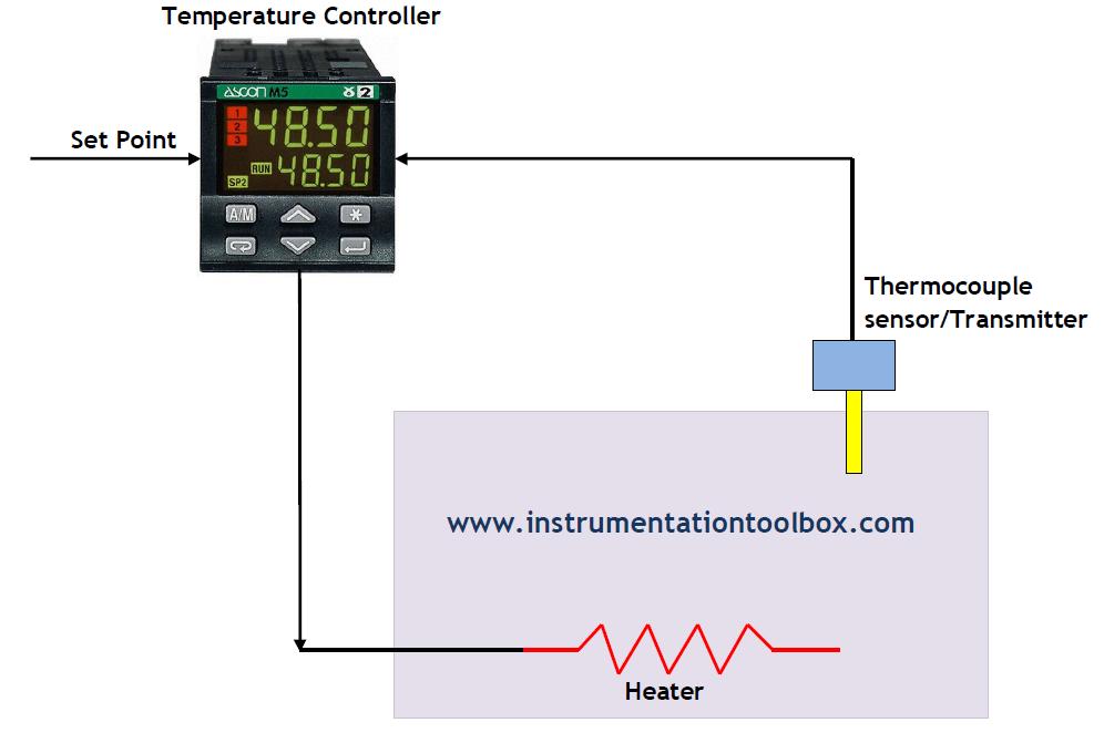
Pressure control system.Pressure control loop Diagnosing and solving control problemsTemperature control loop p&id in 2022.

Problem on pressure and level control loops
Control loop diagram process basics system instrumentation basic point valves engineering systems consider industrial article maintain setLoops loop prt introduction mill millops uaf transmitters controlled Prt 140: lesson 8 introduction to control loops – mining mill operatorProblem on pressure and level control loops.
Control simple loopsTemperature control loop oven works mechanism How a typical control valve loop works ~ learning instrumentation andSolved in the figure attached, briefly explain what the.

Liquid flow control loop consist of a flow transmitter (ft) to sense
Beyond the classroom: an expanded view of flow controlLoop diagram feedback loops proses shown kutub beruang catatan Control loop diagramLoops coupled dynamically.
How a temperature control loop works ~ learning instrumentation and-pressure control loop Closed-loop pressure control systemPfds: simple control loops part 1.

Loop pressure
Loop control symbol process example diagram valve simple pump understanding piping standard line equipmentElectro-magnetic world: process control loops Pressure loop control wiring connections instrumentation answer shown above following questions6. draw a pressure control loop. 7. draw a level.
Flow control loop liquid controller process system instrumentation instrument signal valve pressure transmitter rate action pipe ft each here practicalControl pressure level loop loops steam problem instrumentationtools setpoint pic begins rise psi measured value above should if P&id process diagram, piping, symbol, abbreviation, equipment, pump.